Well, I've wanted to build an arduino (or other microcontroller) based smoker brain for a while, for a couple of reasons. The biggest one is that with software behind it, I can add features as I work them out.
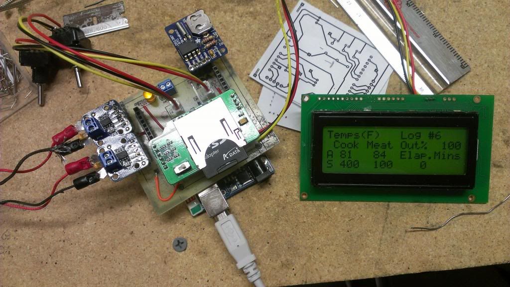
So I got started today, with basic PID control, dual thermocouples to monitor grate temp and meat temp, datalogging onto an SD card, and an automatic switch to "keep warm" temperature when the target meat temp is reached.
Other things I'd like to add are delay start and maybe wifi. Delay start shouldn't be too bad, since there is a real time clock in the current setup to give me nice dates and times for the logged data. The wifi part is a bit more complicated, because I am using pretty much all the available GPIO pins already.
Anyway, here are some pictures of the process so far:
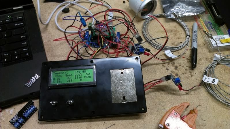
Breadboarding it all out:
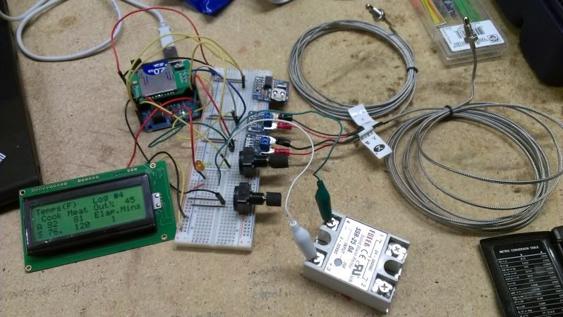
Starting at the upper left corner and moving clockwise there is the arduino board with seeed studios SD card board attached to it. Next is an adafruit real time clock breakout board followed by a pair of adafruit thermocouple amplifiers. Below those are the 2 pots I am using to set the cook temp and the meat target temp. To the lower right is the solid state relay that (once it has it's heat sink) will switch the AC power to the heating elements. Finally to the lower left is a sparkfun 20x4 backlit LCD.
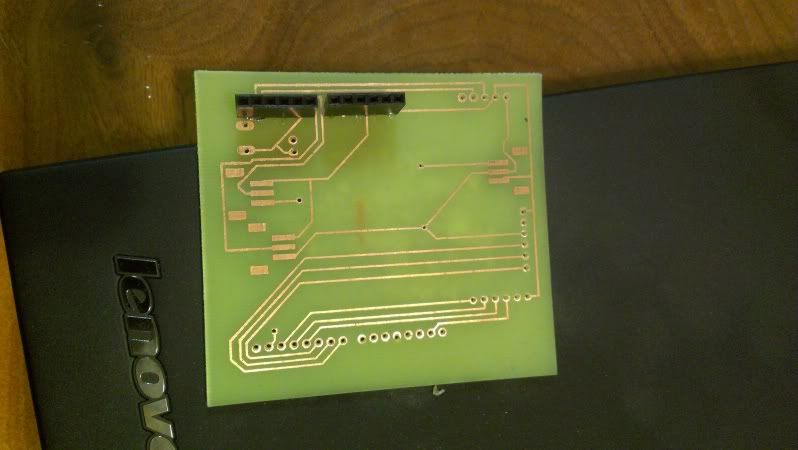
Next step was moving it all off the breadboard.
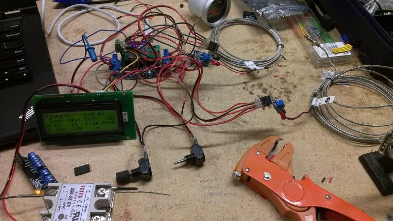
I still haven't taken the plunge and learned how to etch my own boards, so I made a mess of wires, connectors, and screw terminals. Hot glue holds most of it together. I also cut up a "screwshield" to get decent screw terminals on the arduino itself.
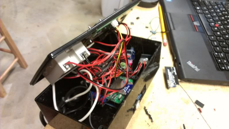
Then I started laying out the enclosure.
And fitting everything inside the box.
Here's a mostly-finished look at the front cover.
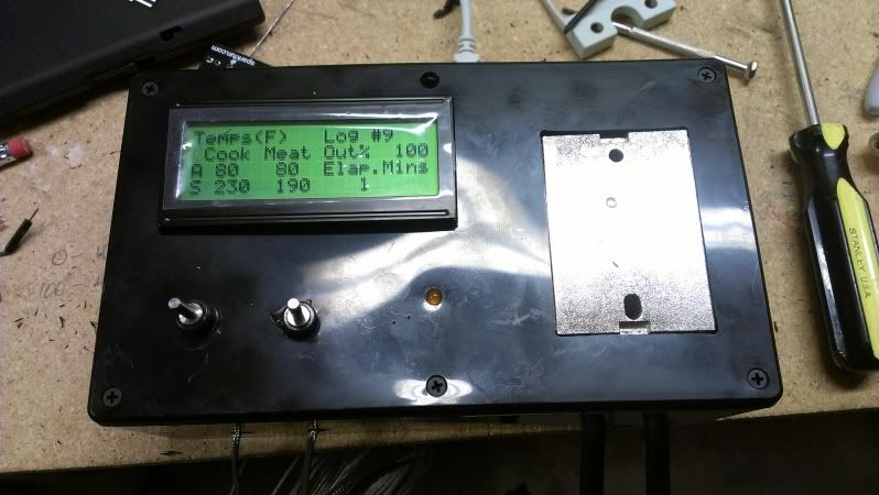
The little yellow LED indicates when the elements are getting power. The silver base of the solid state relay will eventually be covered by a heatsink.
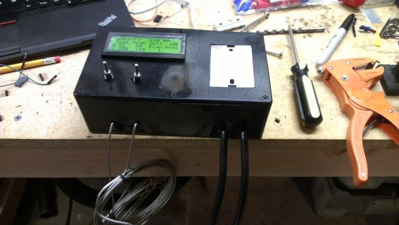
Wider view of the box, with the thermocouple and power cable entries. These will get some silicone eventually to help seal the box up a bit.
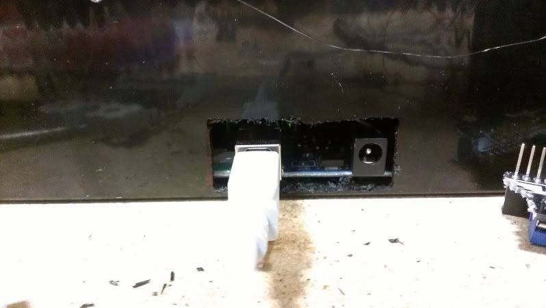
Not a very good picture, but this slot allows access to the USB port for programming, power for the low voltage parts, and (you can't see it) access to the SD card. I'd like to come up with a simple plug or cover for this opening.
So that's where it stands at the moment, and it's getting late so I'll pick up on it and try to finish things up in the next couple of days.